RC BAJA: SUSPENSION AND STEERING

Analysis
Throughout this project a lot of different analysis have be done to complete and plan the construction of this car. The most used methods were from mechanics of materials. Analyzing the sizes and strengths that the materials.
RC Car Requirements
· The RC Baja Car suspension must be able to maintain integrity and secureness while reaching a top speed of 25mph.
· The suspension must be able to absorb the impact of a drop from 3’
· The suspension must maintain integrity after 6 hours of use
· The suspension must be able to support a weight of 15lbs without going past one inch of clearance
· The steering equipment must fit the chassis and be able to allow the wheels to turn 45 degrees
· The battery must be able to maintain top speed for 10 minutes without reduction in top speed
The RC car must be able to operate from a distance of 25ft away
Green Sheet Analysis
Figure A1 shows the minimum thickness required to support the suspension shock. The found thickness was .12 inch. Although the found thickness was .12 in a thickness of .25 in was decided on because it will be easier to work with and give the ability to put screws through to mount it.

Figure A1: Green Sheet Analysis 4
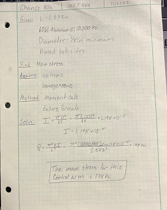
Figure A2: Green Sheet Analysis 7
Figure A2 shows the analysis of the stress on the tie rod that supports the wheel. The analysis used buckling equations to calculate the max amount of stress on the tie rod. It was determined that this dimensioned tie rod would be well suited to support the drop test without breaking. The determined max stress was 178 psi.
Figure A2 shows the minimum pin size required to support the suspension arm without failing. The found diameter was .054 inch.
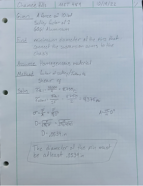
Figure A3: Green Sheet Analysis 3
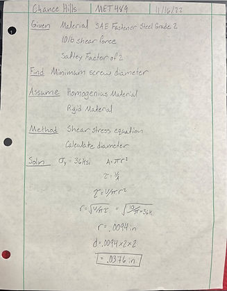
Figure A4 shows the minimum required screw diameter for mounting. A shear stress equation with an area equation was completed to find the minimum diameter value. The minimum diameter that was found was .0376 in which is well below the diameter that will be used.
Figure A4: Green Sheet Analysis 12
Figure A3 shows the distance that will be necessary for the shock to fit into the brace and the wheel. The found shocks are 90 mm or around 3.54”. The shock will also be at an angle.

Figure A5: Green Sheet Analysis 1